


Garden electrics
20/03/20 16:53
So many garden electrics cause problems over the years due to poor installation, I've recently refurbished a large garden with multiple garden lights which were tripping the RCD within the property. I was initially called out to solve the problem of the RCD tripping and soon realised that to lighting working again needed quite a bit of work.
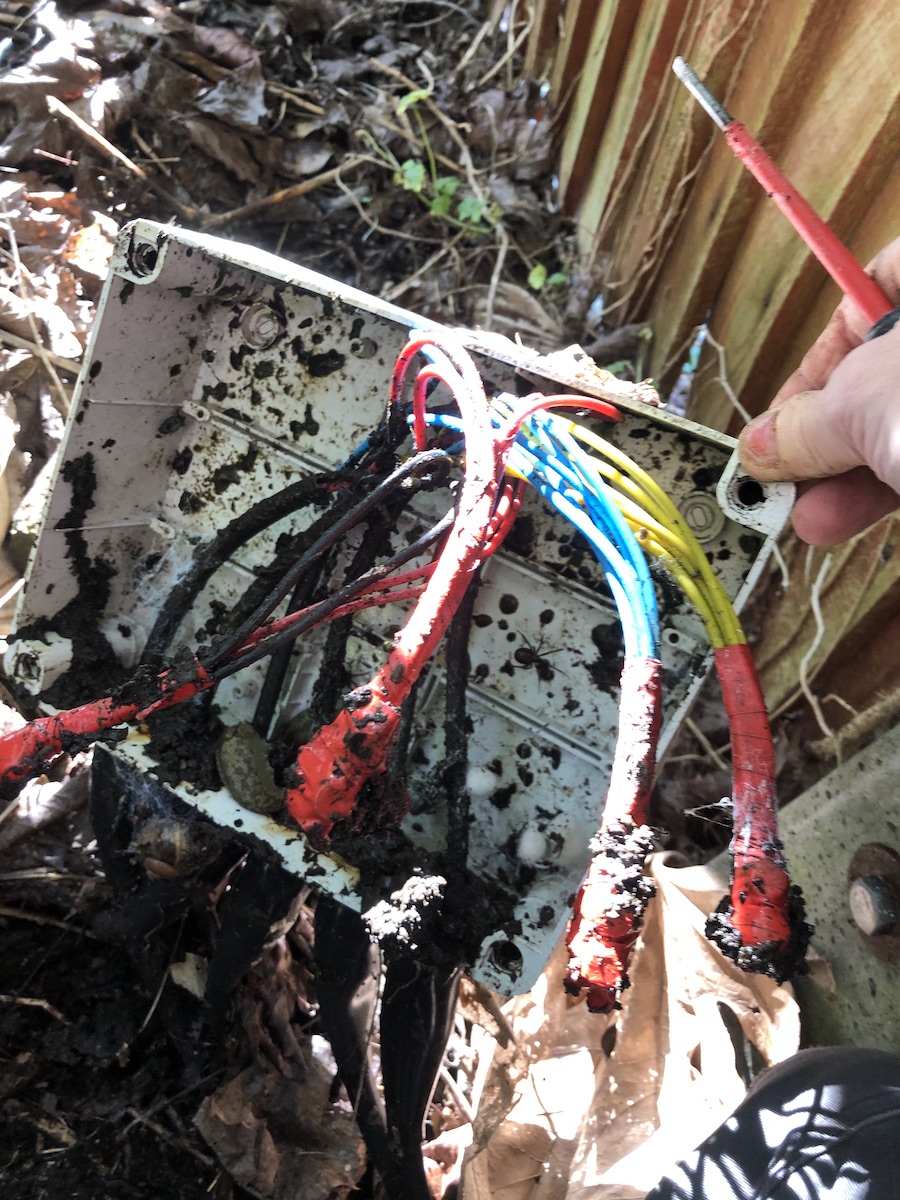
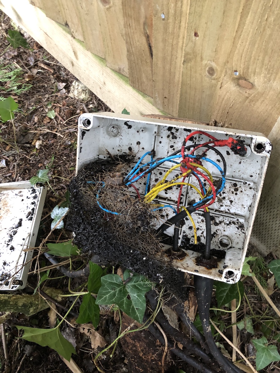
This is the first enclosure that I came across in the garden. As you can see it's really rather poorly maintained. It did have a lid on it to be fair, but clearly a lot of moisture and flora and fauna ingress.

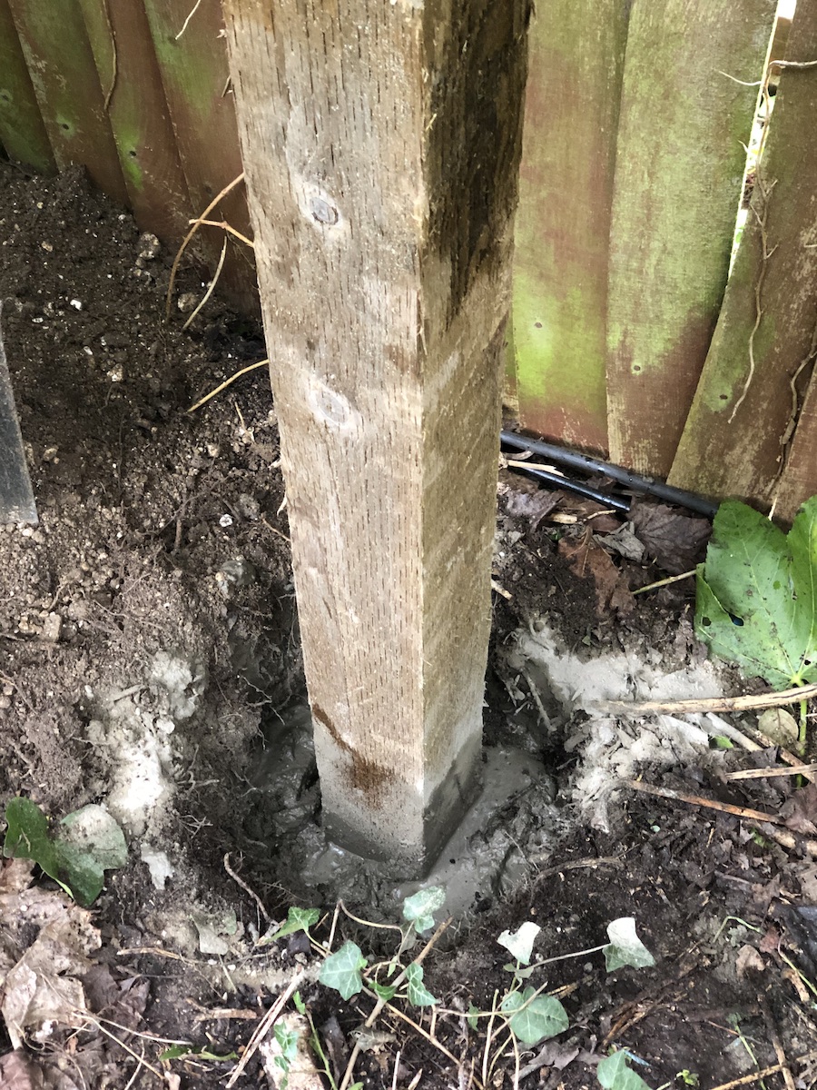
First thing to do was to install a new treated post into the ground to site the replacement enclosure.
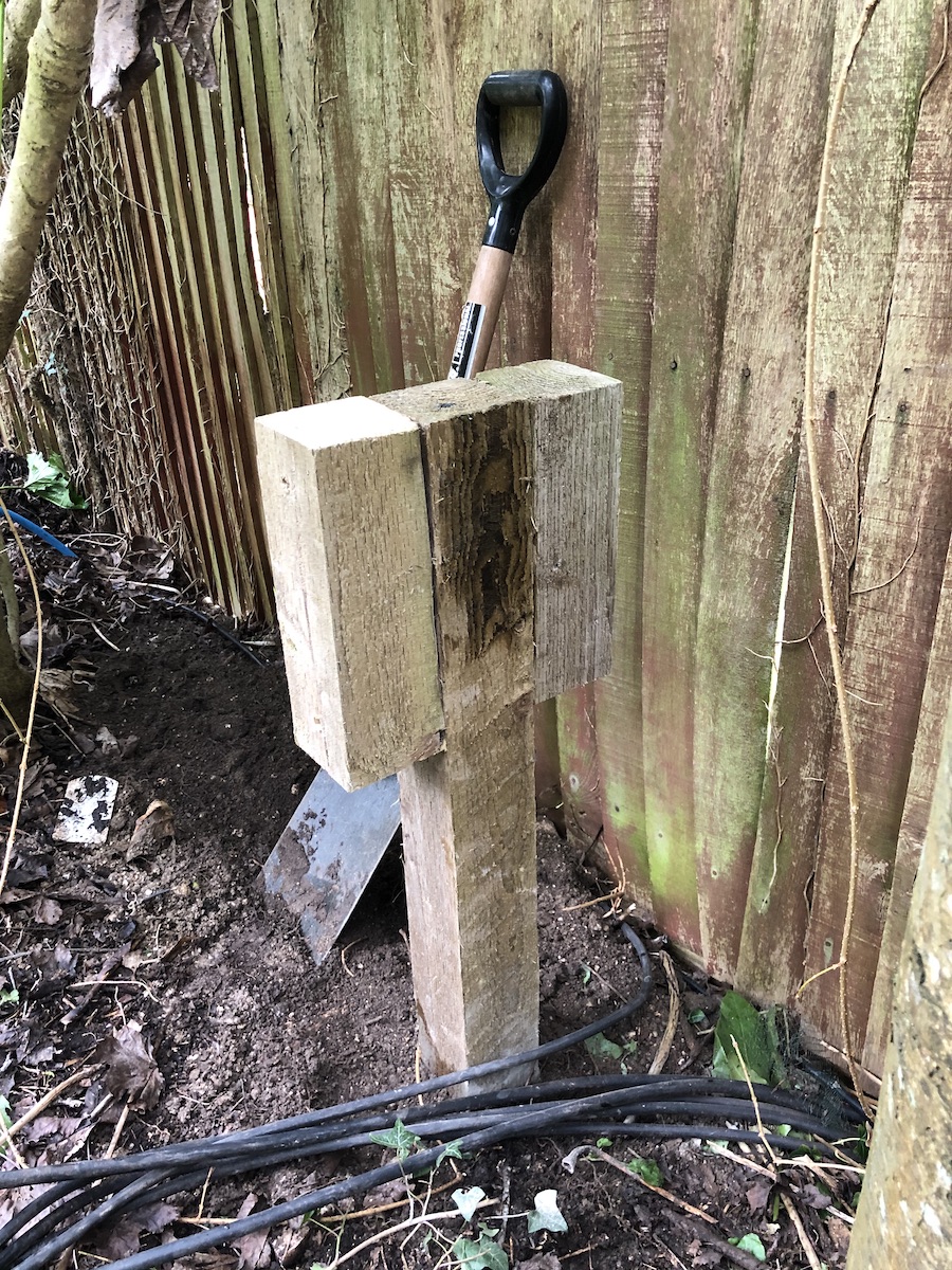
Then I added additional support to the sides so that the new enclosure was suitably supported.
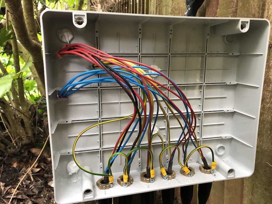
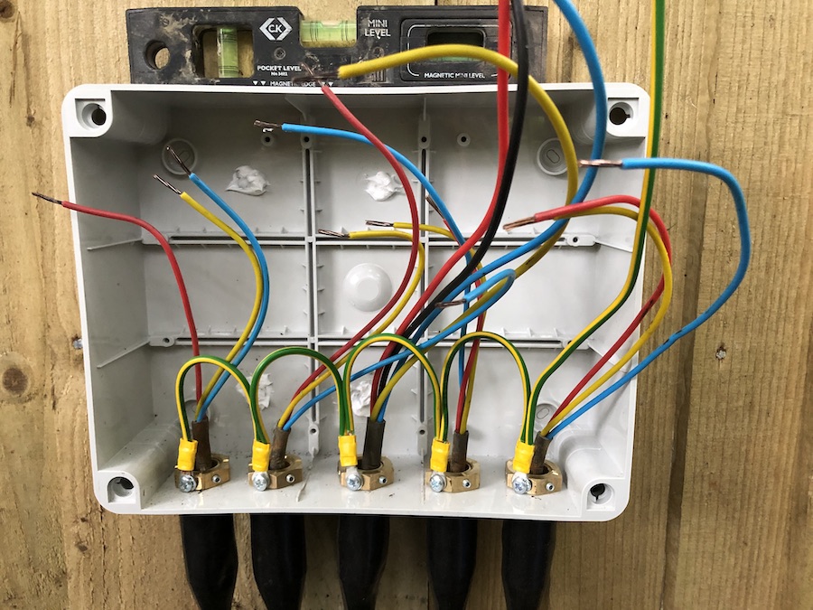
I then re-terminated all the SWA cabling that was run under the ground and emerged at this point. Previously the installation had no earth continuity on the outer sheath of the cable, you can see here that the use of the brass piranha nuts allow for bonding the earth across the cables.
This was the second enclosure, The following four photos show the before and after.


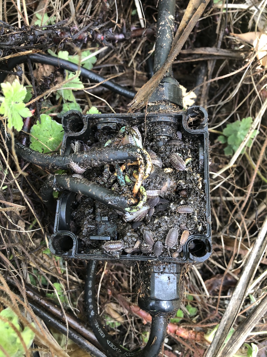
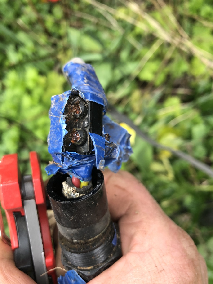
This was one of the existing junction boxes feeding the individual lights. You can see that the side has been cut away rather than using additional compression glands.
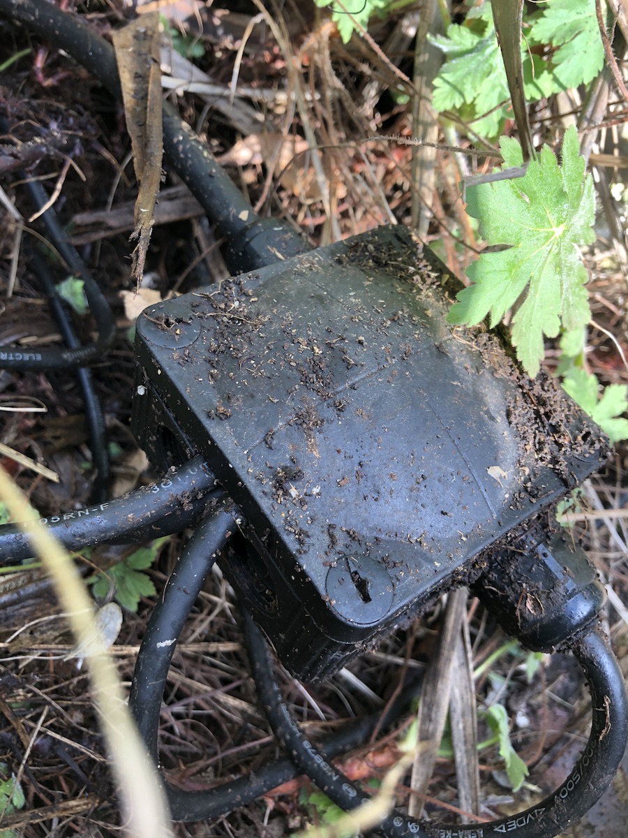
As a result, plenty of woodlice found their way in…
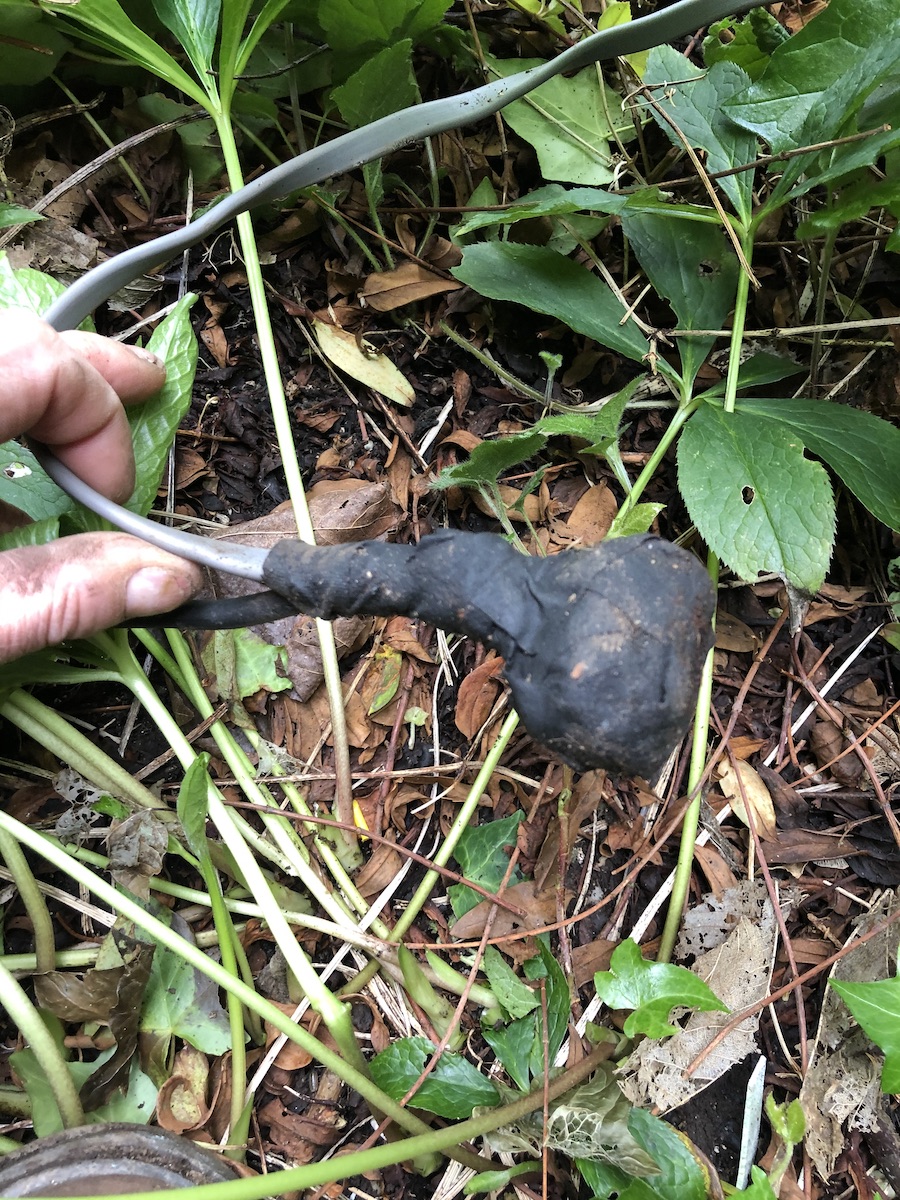
This is another (waterproof) termination that had been installed previously.
And another…
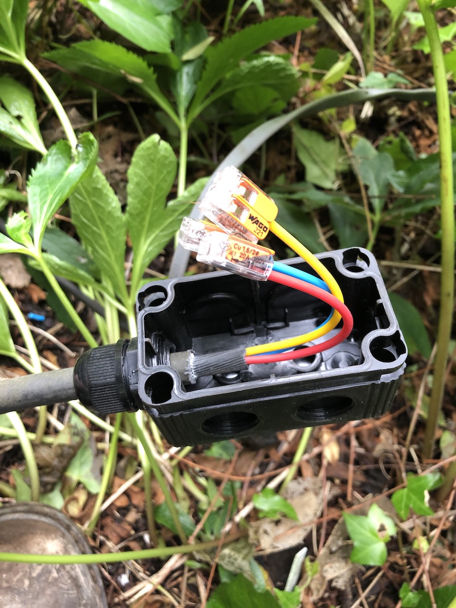
Finally, here is an example of the new junction box installed. You can see that the outer sheath of the SWA has not been earthed. This is because they were all earthed at the larger enclosures. The earth in this case is the third core of the cable itself.
This is the first enclosure that I came across in the garden. As you can see it's really rather poorly maintained. It did have a lid on it to be fair, but clearly a lot of moisture and flora and fauna ingress.
First thing to do was to install a new treated post into the ground to site the replacement enclosure.
Then I added additional support to the sides so that the new enclosure was suitably supported.
I then re-terminated all the SWA cabling that was run under the ground and emerged at this point. Previously the installation had no earth continuity on the outer sheath of the cable, you can see here that the use of the brass piranha nuts allow for bonding the earth across the cables.
This was the second enclosure, The following four photos show the before and after.
This was one of the existing junction boxes feeding the individual lights. You can see that the side has been cut away rather than using additional compression glands.
As a result, plenty of woodlice found their way in…
This is another (waterproof) termination that had been installed previously.
And another…
Finally, here is an example of the new junction box installed. You can see that the outer sheath of the SWA has not been earthed. This is because they were all earthed at the larger enclosures. The earth in this case is the third core of the cable itself.
18th Edition
21/11/19 19:58
I've recently been on a three day course to get my skills updated to the 18th Edition wiring regulations. It is possible to study and simply take the exam in order to achieve the new requirements for electrical installers although I chose on this occasion to study at a training centre. The main reason I did this is that the 18th Edition has a few new items that are causing a bit of a stir in the electrical world and I wanted to study as part of a group so that we could discuss these changes and see how other installers are interpreting these new regulations.
It's worth noting that the 18th Edition regulations fully came into effect in January 2019, and although I've been working to the new regulations (a prerogative we have to allow us the time to study) , I have only recently taken the exam.
Some of the main changes causing confusion are as follows:
1. SPDs or Surge protective devices. These are additional modules housed within the main consumer unit or often sited in another enclosure next to the existing board. These are designed to mitigate electrical over voltages from an external influence that may occur within the electrical installation originating . In short, this is basically all about lightning strikes and preventing damage to some of the more sensitive electrical items we now have within our homes. That's not to say it isn't about preventing fires as well, it does also help against that. To be clear, we aren't talking about a direct strike on the property here, we are talking about a nearby strike that can introduce a surge into the property. These devices mitigate the surge by 'dumping' the over voltage to earth so as to keep the nominal voltage in the property as close to the usual 230v as possible. The confusion around these is in fact when it's appropriate to install them. I understand why it is causing confusion as the method for calculating the need for such a device is, in my opinion rather arbitrary. However, I personally think that installing these devices when fitting a new consumer unit in a domestic dwelling is in the main part a good idea. The additional cost of the components vs the possible loss of equipment due to damage makes it such that to not install them would be unwise. (Although I do always give my customers an informed choice on these matters and some do in fact opt against it). There are circumstances where I would definitely install them, and that's in rural locations, especially those with overhead power supplies.
2. AFDDs or Arc fault detection devices. These are also additional component that are installed within the consumer unit and are designed to 'trip' if an arc fault is detected. That's the kind of fault that can occur at loose connections within an installation for example. Not all arcs are detected though, as by design, any switch that turns on an off a mains voltage will at the point of switching cause a tiny arc at the point that the contacts are just making or breaking. This is normal arcing and the device is clever enough to ignore these. It will however trip when a loose connection is causing a heat build up due to a fault producing around 1Kw of power. That's quite an arc occurring at that point and is likely to cause some localised burning, or worse still a fire. The issue around whether to install these or not, is that they are currently prohibitively expensive, sizeable, required for every individual circuit and also difficult to source! While I think these are fantastic devices, and would be a major advantage in all installations (electrical fires are still a big risk), until they come down in price and are incorporated into the current RCBOs that we use, then they won't be getting installed in a normal setting.
3. RCDs or Residual Current Devices. These aren't new; they are the device that detects a leakage of current to earth caused by a fault and trip out to prevent electric shock to those in contact with a live part. What is new however are the types of RCD being manufactured and the requirement to use certain types in certain situations. Nowadays we have far more appliances in our house that use an element of DC power as well as the AC supply power. A normal AC type RCD will not necessarily trip effectively if a fault occurs on a DC part of an appliance whereas a type A device will (as well as tripping on an AC fault). I feel that there is no benefit in installing the older AC type RCDs anymore, although many manufactures have yet to flood the market with A type RCDs until (I think) they have sold all the old stock of AC type ones. I expect a reasonably fast uptake on A type RCDs once they are readily available. There are other new types of RCD out there now too, but I won't go into those here.
4. Split load RCD boards vs RCBOs. RCBOs are devices that incorporate an RCD and an MCB (mini circuit breaker) in one device. This allows for each circuit to be protected individually against earth faults. Under the 17th edition regulations it was common practice to install a consumer unit with two RCDs within (split load board). One of these RCDs protected half the circuits, and the other, the other half. This meant that if a fault occurred on a circuit on one half of the board, all circuits on that half of the board would trip out when the controlling RCD tripped. While this could be somewhat annoying, it was done in the main for cheapness (RCBOs were expensive) but had the disadvantage that half the house tripped out. This was still better than under the 16th edition when only one RCD was used on all socket outlets and as such when that one tripped, all sockets stopped working. In those days lights weren't protected by RCDs so they would have stayed on. The 18th edition now states (in a roundabout sort of way) that there is a case for installing RCBOs to each circuit rather than split load boards. This is because much of our modern equipment in a house normally leaks a certain amount of current to earth. If only 2 RCDs are used then it's possible that many pieces of equipment could leak enough current to earth to cause nuisance tripping which would be a pain! By controlling each circuit with its own RCD (in the form of an RCBO) would help to reduce the chances of nuisance tripping. Given that RCBOs have recently come down in price recently I think these are likely to be installed far more often than they currently are. Personally, from my own testing, I think it's unlikely that the nuisance tripping on a split load board is very likely in a domestic dwelling, however, I always offer RCBOs as an additional option when replacing a consumer unit nowadays.
There are many other changes in the 18th Edition but the above appear to be those that are causing most uncertainly as to how we go forward. This of course is only my take on them, but I hope it's helped you to understand those changes.
New socket installation
05/10/19 16:31
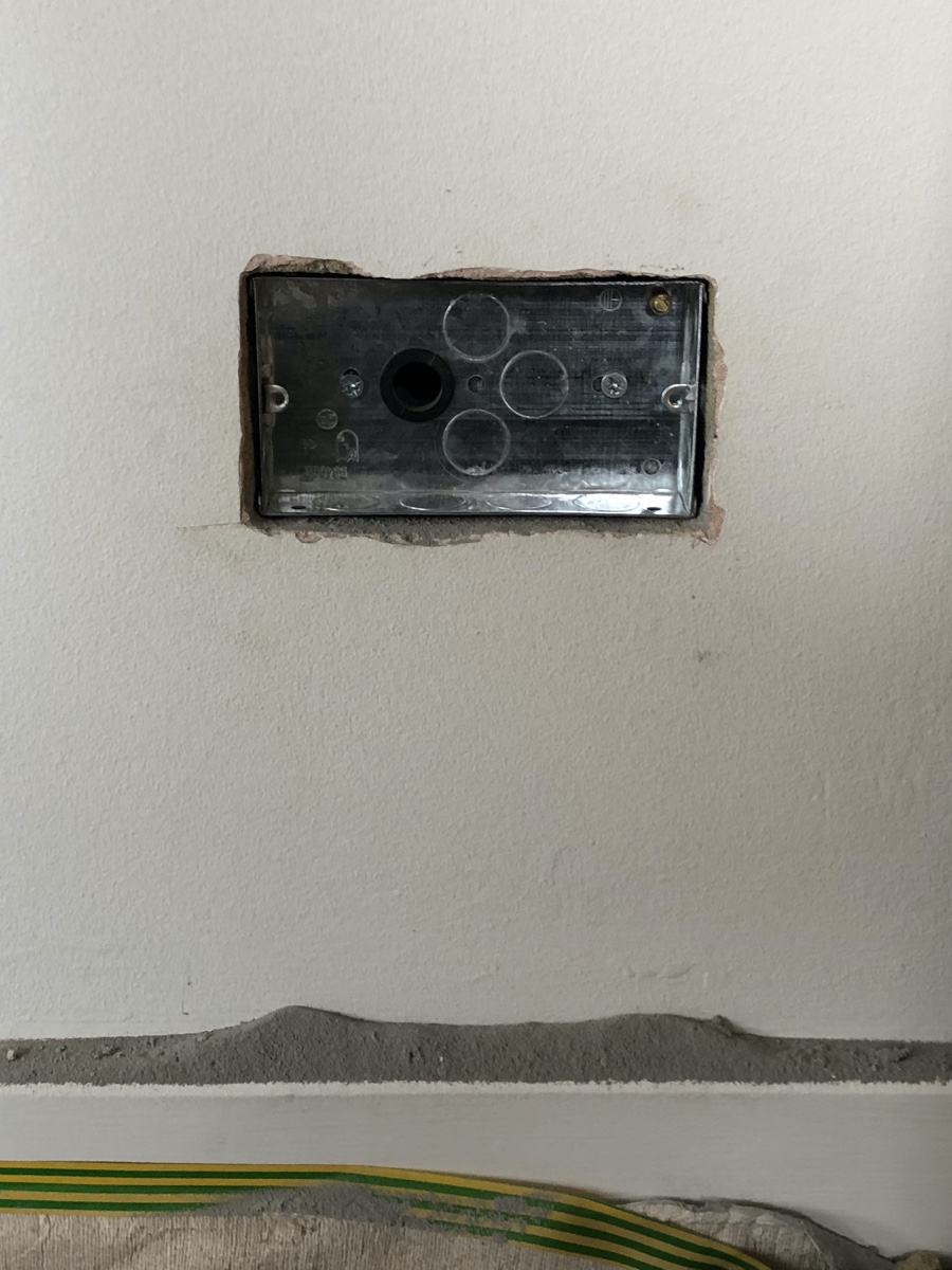
Here a some photos of a recent installation of a new socket outlet. This one was into a thermalite block in a single skin wall. The other side of this wall was into a boiler cupboard with power already available to spur from. This meant that the install was pretty straightforward. The photos show various stages of competition to give you an idea of the work involved. You can see the hole through the wall and the rubber grommet used to pass the cable through.This box was all cut out by hand in this instance as the wall was already decorated and finished so I didn't want to cause any damage. Cutting out by hand isn't always possible, but it can mean a neater finish. I was a little disappointed with the marks I did make on the wall, but in the main it went in well. Certainly the customer was pleased with the result.

Central heating
05/10/19 11:53
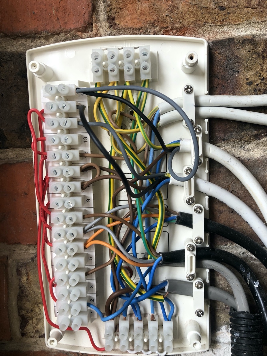
So, one of the things I often have to install or in this case remedy is central heating wiring. In my experience central heating wiring is one of those things that has very often been installed by persons that actually do not seem to know quite what they are doing. Many the times' I've been called to fix an issue after someone else has been tinkering with it! Below is a reasonably simple two zone control or S plan system. However someone had joined both valves to a single thermostat. The terminal 2 seen below is actually a live return from a second wireless transmitter. I was called out as all the heating in the house was coming on in both zones regardless of the setting of the thermostat in one part of the house. I think this had been done as one of the valves was stuck open and so was in effect bypassed. I replaced the actuator on the 2 port valve and rejigged the wiring so it all worked as it should.
I've found that many electricians are unwilling to undertake work in central heating control centres as they find them a bit daunting. Personally I find them quite enjoyable to troubleshoot and get quite a few call outs to do so.
I've found that many electricians are unwilling to undertake work in central heating control centres as they find them a bit daunting. Personally I find them quite enjoyable to troubleshoot and get quite a few call outs to do so.
More junction boxes
01/09/19 08:36
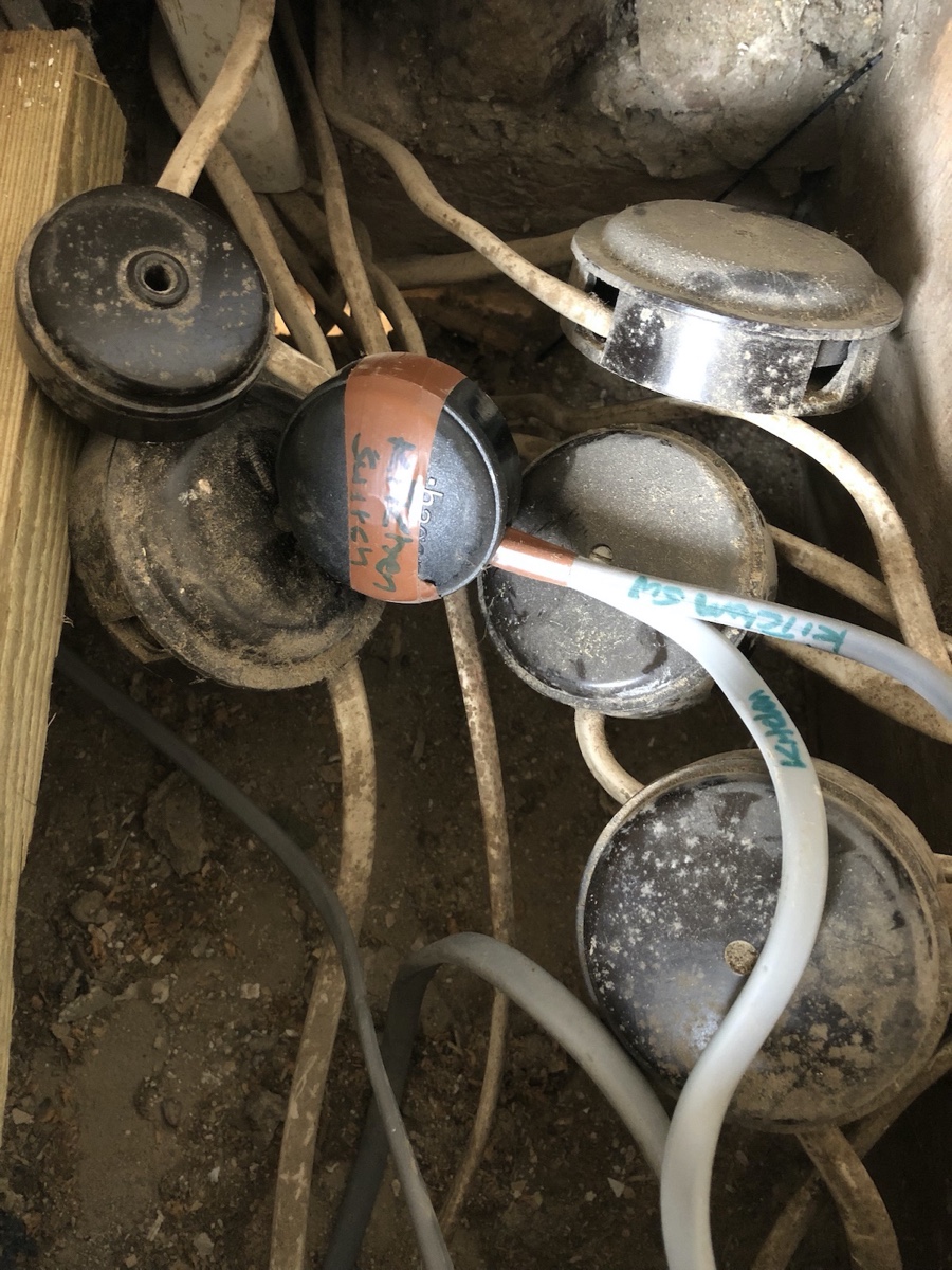
Following on from my previous entry regarding junction boxes. I just thought I'd share with you a photo of a fairly normal installation found in Brighton and Hove (and I'm sure elsewhere) that has (over the years) been heavily modified and extended. As you can see, this often leads to many junction boxes being tacked on to the existing wiring. This is far from ideal, but is unfortunately extremely common place, and these are lurking under many a floorboard! Interestingly, this installation even includes a recent addition (the grey wiring) that has been modified in the last 10 years.
Junction boxes
12/06/19 19:37
Junction boxes are sometimes required when extending or modifying a circuit in some way or other. Traditional junction boxes very often look like this:
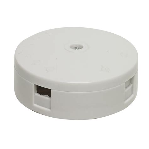
These junction boxes have screw terminals within which can come loose over a period of time leading to problems (see previous post). Screw terminal junction boxes should only be installed where they are readily accessible however, this historically has not been the case. Many of these are found under floors which have had laminate flooring put down over the top of, or glued down carpets or other floor coverings. This then makes then inaccessible and prone to failure due to a lack of maintaining.
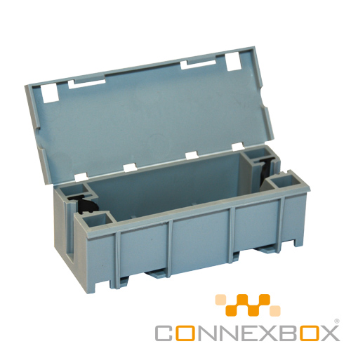
Newer options include Wago terminals which use spring clips to hold the cores of the cables in place and are deemed to be maintenance free. These terminals are then put into an enclosure as a more compliant solution to the old style junction boxes.
See below.

These junction boxes have screw terminals within which can come loose over a period of time leading to problems (see previous post). Screw terminal junction boxes should only be installed where they are readily accessible however, this historically has not been the case. Many of these are found under floors which have had laminate flooring put down over the top of, or glued down carpets or other floor coverings. This then makes then inaccessible and prone to failure due to a lack of maintaining.
Newer options include Wago terminals which use spring clips to hold the cores of the cables in place and are deemed to be maintenance free. These terminals are then put into an enclosure as a more compliant solution to the old style junction boxes.
See below.
Loose Connections
09/06/19 17:23
Occasionally I see loose connections within accessories and the effects of those. So in this entry I wanted to explain what happens in a circuit where a loose connection is present.
You’ll hear lots of people tell you that a loose connection causes more current draw and as a result produces heat. This isn’t actually true and I’ll explain why.
Imagine a shower circuit like the one below (This is a very simplified illustration):
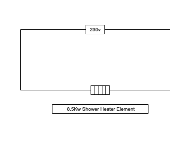
Here we have a typical electrical shower of 8.5Kw running from a 230v power source as in a domestic dwelling.
We can evaluate that the resistance of the shower element is:
R = V^2/P
R = 230^2/8500
R = 6.23Ohms
We can also establish the current flow through it as:
I = V/R
I = 230/6.23
I = 36.91Amps
Or
I = P/V
I = 8500/230
Again I = 39.91 Amps
So, we can redraw the circuit as:
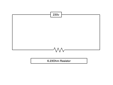
Now, if we add a loose connection, say at the shower isolator:

We can calculate the total resistance in the circuit to be 6.23 + 5 = 11.23 Ohms
Using that to calculate the new total current flow in the circuit we see:
I = V/R
I = 230/11.23
I = 20.48 Amps
Compare this with the original current flow of 36.91 Amps and we can see that there is actually less current draw in the faulty circuit than in the healthy one.
The problem arises though when we consider the power dissipated by the shower element alone:
P = I^2R
P = 20.48^2 x 6.23
P = 2613W
This means that in order for the heater element to bring the water up to temperature it has to work for longer.
Now, if we look at the power being dissipated by the 5 Ohm fault resistance we see:
P = I^2R
P = 20.48^2 x 5
P = 2097W
So, we can see that a huge amount of power is being dissipated at the fault. This is the result.
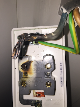
So, we do get a huge amount of power and heat at the fault which is a common cause of fire, but the current flow is not actually in the circuit as a result of the fault.
You’ll hear lots of people tell you that a loose connection causes more current draw and as a result produces heat. This isn’t actually true and I’ll explain why.
Imagine a shower circuit like the one below (This is a very simplified illustration):
Here we have a typical electrical shower of 8.5Kw running from a 230v power source as in a domestic dwelling.
We can evaluate that the resistance of the shower element is:
R = V^2/P
R = 230^2/8500
R = 6.23Ohms
We can also establish the current flow through it as:
I = V/R
I = 230/6.23
I = 36.91Amps
Or
I = P/V
I = 8500/230
Again I = 39.91 Amps
So, we can redraw the circuit as:
Now, if we add a loose connection, say at the shower isolator:
We can calculate the total resistance in the circuit to be 6.23 + 5 = 11.23 Ohms
Using that to calculate the new total current flow in the circuit we see:
I = V/R
I = 230/11.23
I = 20.48 Amps
Compare this with the original current flow of 36.91 Amps and we can see that there is actually less current draw in the faulty circuit than in the healthy one.
The problem arises though when we consider the power dissipated by the shower element alone:
P = I^2R
P = 20.48^2 x 6.23
P = 2613W
This means that in order for the heater element to bring the water up to temperature it has to work for longer.
Now, if we look at the power being dissipated by the 5 Ohm fault resistance we see:
P = I^2R
P = 20.48^2 x 5
P = 2097W
So, we can see that a huge amount of power is being dissipated at the fault. This is the result.
So, we do get a huge amount of power and heat at the fault which is a common cause of fire, but the current flow is not actually in the circuit as a result of the fault.
First Blog entry
31/05/19 20:16
So, today I thought I'd start a blog on the site. The idea of this is to give an idea of the life an electrician, but also to show off some interesting developments in the world of electrical installations and also a bit of education into what we as electricians need to know. Anyway, first thing's first. Here's the first post!